Control LED Using HC-05 Bluetooth, Arduino and Mobile App
Control LED Using HC-05 Bluetooth, Arduino and Mobile App
Bluetooth is a wireless communication technology with a limited range. To control LEDs using HC-05 Bluetooth, Arduino, and a mobile app, you should proceed with the following experiment. In this setup, the Bluetooth module interfaces with Arduino, facilitating the exchange of data with an Android application through Bluetooth communication. This experiment enables the remote control of LEDs by sending data from a mobile app to the Arduino.
The setup involves the integration of an Arduino with a Bluetooth module (HC-05) to turn LED lights on and off through data transmission from a mobile app.
Components Required:
- Arduino Uno
- Bluetooth Module (HC-05)
- Jumper Wires
Arduino Uno:
Arduino is a user-friendly, open-source electronics platform comprising both hardware and software components. Its design is geared towards enabling individuals involved in creating interactive projects.
Bluetooth Module:
The HC-05 is a serial port module known for its ease of use. When examining the pin configuration of the HC-05, you'll find a total of 6 pins, but typically, only the 4 middle pins are needed for applications.
Specifications:
- Frequency -- 2.4GHz ISM band
- RF transmit power -- +4dBm
- Sensitivity -- ≤-80dBm
- Power supply -- 1.8V Operation, 3.3 to 5 V I/O, 50mA
- Working temperature -- -20 ~ 75Centigrade
- Dimension -- 26.9mm x 13mm x 2.2 mm
Jumper Wires:
A jumper wire is an electrical wire equipped with connectors or pins at each end. It is commonly employed to interconnect components without the need for soldering, providing a convenient method for establishing electrical connections between different parts of a circuit.
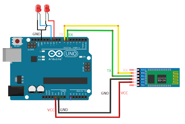
Connection Diagram:
Connect your components according to the provided diagram and link the USB cable from Arduino to your computer.
For the Bluetooth module, connect TXD to Rx and RXD to Tx. Transmit and Receive references pertain to each device, meaning that a transmission emanating from the TXD pin of the Bluetooth module must be received by the Arduino on the Rx Pin. Conversely, a transmission going out of the Arduino Tx Pin should be connected to the RXD pin of the Bluetooth module. LEDs are connected to Arduino digital I/O pins.
In this scenario, the SoftwareSerial library is employed to convert digital pins into RXD/TXD pins. This library allows serial communication on other digital pins of the Arduino, replicating the functionality using software. Multiple software serial ports can be established with speeds up to 9600 bps. In this setup, Arduino pins 6 and 7 are configured as software serial.
Arduino Code:
#include
<SoftwareSerial.h>
SoftwareSerial
mySerial(6, 7); // RX, TX
int led1 = 10;
int led2 = 11;
String state;
void setup() {
// sets the pins as
outputs:
pinMode(led1,
OUTPUT);
pinMode(led2,
OUTPUT);
// initialize
serial communication at 9600 bits per second:
Serial.begin(9600);
mySerial.begin(9600);
}
void loop() {
while (mySerial.available()){ //Check if there is an available byte to read
delay(10); //Delay added to make thing stable
char c = mySerial.read(); //Conduct a serial
read
state += c; //Storing Bluetooth command in
String
Serial.println(state);
}
// if the state is
'LED1ON' the Led1 will turn on
if
(state.equals("1")) {
digitalWrite(led1,
HIGH);
Serial.println("Light
On");
}
// if the state is
'LED1OFF' the led1 will turn off
else if (state.equals("2")){
digitalWrite(led1,
LOW);
Serial.println("Light
Off");
}
// if the state is
'LED2ON' the Led2 will turn on
else if (state.equals("3")){
digitalWrite(led2,
HIGH);
Serial.println("AC
On");
}
// if the state is
'LED2OFF' the led2 will turn off
else if (state.equals("4")){
digitalWrite(led2,
LOW);
Serial.println("AC
Off");
}
// if the state is
'ALLON' the Led's will turn on
else if (state.equals("5"))
{
digitalWrite(led1,
HIGH);
digitalWrite(led2,
HIGH);
Serial.println("All
On");
}
// if the state is
'ALLOFF' the Led's will turn off
else if
(state.equals("6")) {
digitalWrite(led1,
LOW);
digitalWrite(led2,
LOW);
Serial.println("All
Off");
}
state="";
//to clear previous data
}
Upload:
Connect Arduino
board to computer using USB cable and wait for few seconds then
it will show you "Com port".
Check your Com Port
and Board Selection before upload Arduino code.
Mobile App:
Develop your Bluetooth application using MIT App Inventor to send commands to an Arduino via Bluetooth communication, enabling you to control the On/Off state of your LEDs. Monitor the text output in the Arduino serial monitor for additional insights.
For Android App Development click on below link:
For Android App Development click on below link:
Bluetooth Control App Using MIT App Inventor
HOME

Subscribe to:
Post Comments
(
Atom
)
Internet of Things
What is Internet of Things?
What is IoT? The Internet of Things (IoT) is the network of physical objects/things are embedded with software, sensors, and hardw...


No comments :
Post a Comment