How to Upload Sensor Data to Cloud - ThingSpeak
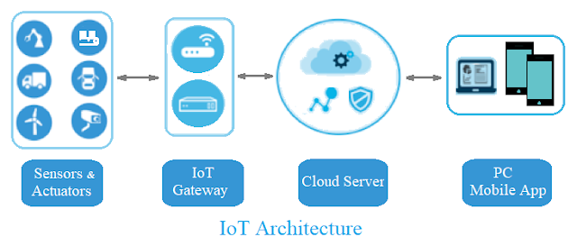
This project focuses on transforming your NodeMCU into a gateway device, facilitating the uploading of sensor data to the ThingSpeak server. This tutorial provides instructions for users to gauge ambient temperature and humidity, with the recorded values transmitted to a personal cloud server on ThingSpeak every 15 seconds. This enables users to visualize both sets of data on a web page. To accomplish data transmission to ThingSpeak using a NodeMCU, it is essential to have a NodeMCU with network connectivity. Additionally, ThingSpeak necessitates a user account and the creation of a channel, which serves as the destination for sending and storing data.
Requirements:
- NodeMcu-12E (ESP8266)
- DHT-11
- Jumper Wires
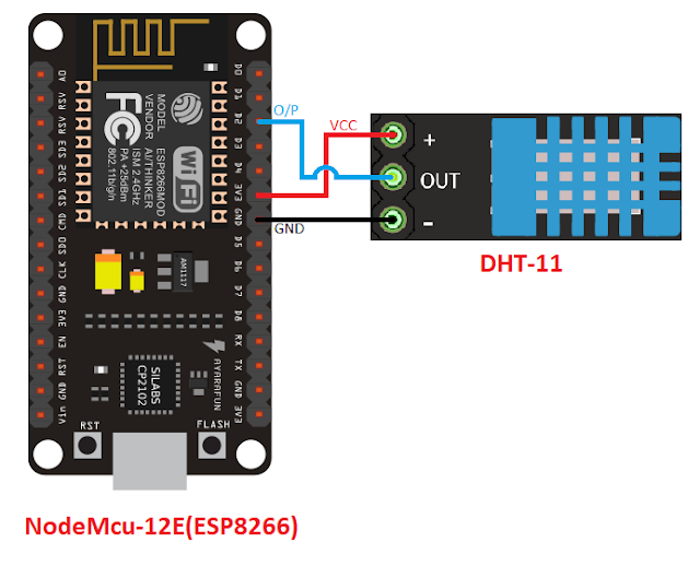
Connection Diagram:
Sign Up For ThingSpeak:
Visit https://thingspeak.com/ and create an account.
Generate a new channel, and subsequently, navigate to API keys. Copy the API key and paste it into your program.
Code:
#include
<ESP8266WiFi.h>
#include
<DHT.h>
#define
DHTPIN D2
#define
DHTTYPE DHT11
DHT
dht(DHTPIN, DHTTYPE);
const
char* ssid = " Your Wi-Fi Network name"; // replace with your Wi-Fi ssid
const
char* password = " Wi-Fi Network Password ";
const
char* host = "api.thingspeak.com";
const
char* privateKey = " Your thingSpeak API Key"; / Enter your Write API
key from ThingSpeak
void
setup() {
Serial.begin(115200);
delay(10);
//
We start by connecting to a WiFi network
Serial.println();
Serial.println();
Serial.print("Connecting
to ");
Serial.println(ssid);
WiFi.begin(ssid,
password);
while
(WiFi.status() != WL_CONNECTED) {
delay(500);
Serial.print(".");
}
Serial.println("");
Serial.println("WiFi
connected");
Serial.println("IP
address: ");
Serial.println(WiFi.localIP());
}
float
value, temp;
void
loop() {
delay(15000);
float
h = dht.readHumidity();
float
t = dht.readTemperature();
Serial.print("connecting
to ");
Serial.println(host);
//
Use WiFiClient class to create TCP connections
WiFiClient
client;
const
int httpPort = 80;
if
(!client.connect(host, httpPort)) {
Serial.println("connection
failed");
return;
}
//
We now create a URL for the request
String
url = "/update";
url
+= "?api_key=";
url
+= privateKey;
url
+= "&field1=";
url
+= t;
url
+= "&field2=";
url
+= h;
Serial.print("Requesting
URL: ");
Serial.println(url);
//
This will send the request to the server
client.print(String("GET
") + url + " HTTP/1.1\r\n" +
"Host:
" + host + "\r\n" +
"Connection:
close\r\n\r\n");
delay(10);
//
Read all the lines of the reply from server and print them to Serial
while(client.available()){
String
line = client.readStringUntil('\r');
Serial.print(line);
}
Serial.println();
Serial.println("closing
connection");
}
Output:
Output:
Open
your Thingspeak account and click on channel private view, output will be shown
as graph.
How to create Cloud - ThingSpeak account and Channels
ThingSpeak Cloud Platform
To utilize ThingSpeak for cloud computing, you have two options: either create a new MathWorks account or log in using an existing MathWorks account.
1.Sign up for ThingSpeak
Fill the Details and Click On Continue Button as show in
below fig..
You will get mail from service@mathworks.com. Open your
Email and click on verify your Email.
Click OK to login to ThingSpeak account.
2. Click Channels >> MyChannels
3. On the Channels page, click New Channel
4. Check the boxes next to Fields 1 & 2. Enter these channel setting values:
5.Click "Save Channel" at the bottom of the settings.
You now see these tabs:
Private View: This tab displays information about your channel that only you
can see.
Channel Settings: This tab shows all the channel options you set at creation.
You can edit, clear, or delete the channel from this tab.
Data Import/Export: This tab enables you to import and export channel data.
6. API Keys Settings
Write API Key: Use this key to write
data to a channel. If you feel your key has been compromised, click Generate
New Write API Key.
Read API Keys: Use this key to allow
other people to view your private channel feeds and charts. Click Generate
New Read API Key to generate an additional read key for the channel.
Note: Use this field to enter information about channel read keys. For example, add notes to keep track of users with access to your channel.
API Requests
Write API Requests is to upload sensor data to Channel.
Read API Requests is to Retrieve sensor data from Channel.
 Output
After uploading data
from the sensor using hardware modules like NodeMcu(ESP8266) Wi-Fi are
raspberry pi output will be like this.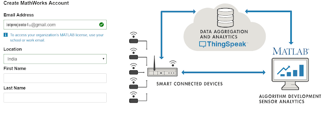
How to Add NodeMcu (ESP8266) Board to Arduino IDE
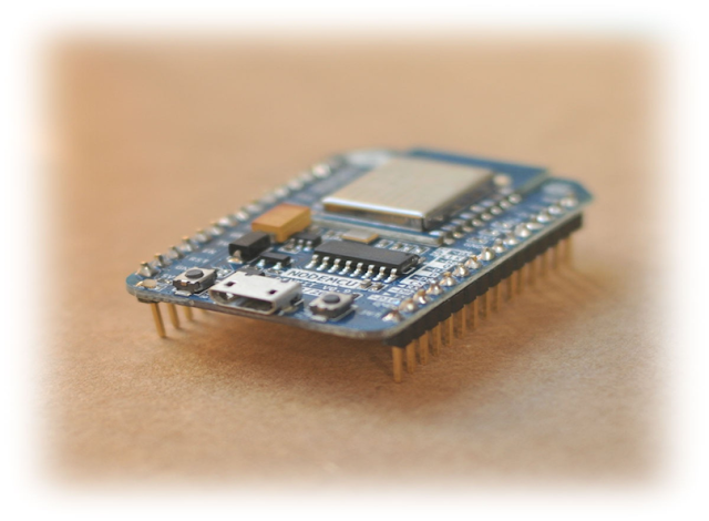
The NodeMCU board is not initially available in the Arduino IDE by default. To program your NodeMCU or ESP8266 board using the Arduino IDE, follow the steps below:
The NodeMCU ESP8266 is a low-cost WiFi module
built by Espressif Systems.
Requirements
- Arduino IDE in your PC
- Internet connection
- NodeMCU (ESP8266 ) Board
Step 1: Adding ESP8266 URL to Arduino IDE
Open your Arduino IDE. To Add additional URL for board manager.
Go to File >> Preferences
Paste below url in Additional Board Manager URLs
as Shown below fig.
http://arduino.esp8266.com/stable/package_esp8266com_index.json
Now Click OK.
Step 2: Open Board Manager
Go to Tools >> Board:
>> Board Manager
Search and Install NodeMCU(ESP8266)
in Arduino IDE as shown in below fig.
Search for ESP8266 in search
box.
Select esp8266 by ESP8266 Community.
(If internet is not available then
you will not find ESP8266)
Click on Install Button.
Download progress starts.
If your facing any errors while installation on progress try
again after few hours.
If your installation is finished Refresh or Restart your PC.
Step 3: Verify installation of ESP8266
Go to Tools>>Boards>> select NodeMCU
Board
Connect your USB cable to PC and Select
Com port.
Upload example code to check is it
working.
Text To Speech App using MIT App Inventor
To design a Text-To-Speech (TTS) app using MIT App Inventor, follow the steps below:
MIT App Inventor website:
Click on this
link ai2.appinventor.mit.edu.
Introduction:
Log in with your Gmail account to initiate the development of your Android application. Navigate to the "Projects" menu or menu bar and choose "Start new project." Provide a name for your project and click the "OK" button to proceed.
Upon completing the previous steps, you will enter the application development section. In this area, you can design the layout of your app using the "Designer" and implement its functionality using "Blocks."
Designer Panel:
Choose "Layout" from the Palette and select "Horizontal Arrangement." Drag and drop this onto your blank screen. This component will serve as the container for all the interface elements in your app.
Navigate to the Properties section in the right corner of the page. Adjust the Height property to 100 pixels and set the Width property to Fill Parent.
Change the properties as shown in below image.
Select the TextBox component from the user interface options. The TextBox is a designated box where users can input text.
Select the Button component from the user interface options and drag it to the right side of the TextBox. The Button is designed to detect clicks. Customize the Button text and color according to your preferences.
Select
Media > TextToSpeech component from user Media and drag it to App
Screen. The TestToSpeech component speaks a given text aloud. It is Non-Visible
Component.
MIT App Inventor Block Editor:
The Blocks
Editor is where you program the behaviour of your app. There are Built-in
blocks that handle things like math, logic, and text with each components you
have added.
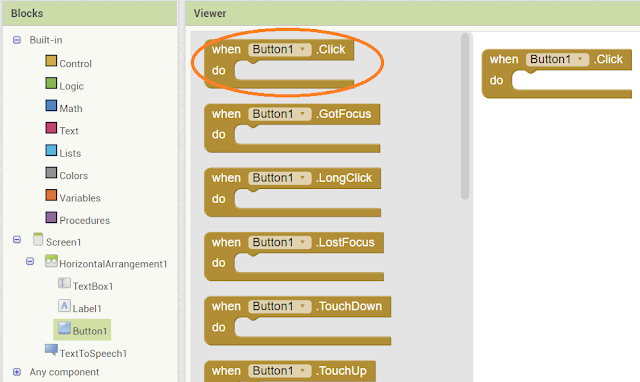
Click on Button
and drag the when Button1 .click block.
Click on TextToSpeech1
component and drag the TextToSpeech1 .Spek, message block and attach it to
Button1 block.
Click on
TextBox1 component and drag the Text block and attach it to TextToSpeech1
block.
Final Text To Speech App Block look like
below image.
Once your app is finished download apk and install it in Android Mobile.
Related Resources:

Bluetooth Control App using MIT App Inventor
To design a Bluetooth Control App using MIT App Inventor, follow the steps below:
MIT App Inventor website:
Click on this link ai2.appinventor.mit.edu.
Log in to MIT App Inventor:
Log in with your Gmail account to initiate the development of your Android application. Navigate to the "Projects" menu or menu bar and choose "Start new project." Provide a name for your project and click the "OK" button to proceed.
Upon completing the previous steps, you will enter the application development section. In this area, you can design the layout of your app using the "Designer" and implement its functionality using "Blocks."
Designer Panel:
Select "Layout" from the Palette and select "Horizontal Arrangement." Drag and drop this onto your blank screen. This component will serve as the container for all the interface elements in your app.
Select properties > Image and upload the image to display.
Navigate to the Properties section in the right corner of the page. Adjust the Height property to 100 pixels and set the Width property to Fill Parent.
Select the ListPicker component from user interface. ListPicker is the
button, which displays the list of available bluetooth devices and handle the
selection.
Select properties
> Text and change the text display. You can also change the height,
width, color using the properties panel.
Select properties > Image and upload the image to display.
Choose image file from your computer.
Select Layout
> from palette and select Horizontal arrangement. Horizontal arrangement
component is to display a group of components laid out from left to right. We
are using this component to display two buttons horizontally which is “ON” and
“OFF”. We need 4 Horizontal Arrangement with same properties.
After this, click and hold on the word “Button” in the palette, drag
your mouse over to the Viewer and drop the button over the horizontal view and
do same by dragging another button. These two buttons will look left to right.
Rename the buttons from “Button1 to LED1ON” and “Button2 to LED1OFF”. Also
change the text and background colour of buttons from properties, which will
display on users screen.
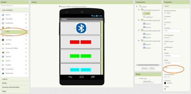
At last, connectivity from palette select Bluetooth Client and drag and drop to the viewer panel. Note that, this is the Non-visible component.
Add a label text , as a status about Bluetooth connection(remove text in properties Text option).
At last, connectivity from palette select Bluetooth Client and drag and drop to the viewer panel. Note that, this is the Non-visible component.
Final app will look like the above image. You can change color, text,
width, height , background of the components.
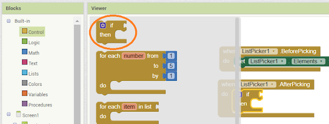
Again click on list picker and select ListPicker After Picking and attach the if Built-in condition from control block.
The Blocks Editor is where you program the behaviour
of your app. There are Built-in blocks that handle things like math, logic, and
text with each components you have added.
Click on the list picker and select ListPicker Before Picking.
Click on listpicker and attach Set elements block as shown in below.
Click on Bluetooth Client and attach AddressesAndNames to Elements.
Again click on list picker and select ListPicker After Picking and attach the if Built-in condition from control block.
Click on Bluetooth Client and attach .connect, Addresses to if condition
like as shown in below.
Click on Listpicker and drag selection block and attach it to Bluetooth
client.
Click on Label and drag Text block and attach it to “then” condition.
Click on Built-in Text and drag empty block and attach it to Text label.
By clicking on the image on App Screen, It will show you paired Bluetooth connections and click on your Bluetooth devise name. It will established communication between selected device and display the text on App screen Bluetooth Connected.
By clicking on the image on App Screen, It will show you paired Bluetooth connections and click on your Bluetooth devise name. It will established communication between selected device and display the text on App screen Bluetooth Connected.
Click on Button and drag the when Button1 .click block.
Click on Built-in Control block and drag if condition and attach to
Button1 as shown in below.
Once your app is finished download apk and install it in Android Mobile.
For Arduino Bluetooth Project Click on below link:
Control LED Using HC-05 Bluetooth, Arduino And Mobile App
Click on BluetoothClient1 and drag isConnected block
and attach it to If condition.
Again Click on BluetoothClient1 and drag .sendText, Text block and
attach it to “then” condition.
Click on Built-in Text and attach empty text box to
BluetoothClient as shown in below.
Follow these steps to remaining Buttons and change
text in Text boxes as you required.
Final app blocks will look like the below image.
Once your app is finished download apk and install it in Android Mobile.
For Arduino Bluetooth Project Click on below link:
Control LED Using HC-05 Bluetooth, Arduino And Mobile App

Subscribe to:
Comments
(
Atom
)
Internet of Things
What is Internet of Things?
What is IoT? The Internet of Things (IoT) is the network of physical objects/things are embedded with software, sensors, and hardw...
